


Section 0: Module Objectives or Competencies
| Course Objective or Competency | Module Objectives or Competency |
|---|---|
| The student will be able to assess and apply Object-Oriented analysis and design methods... | The student will be able to explain the purpose of UML Diagrams and broadly discuss how the diagram types are used. |
Section 1: Overview
The Unified Modeling Language (UML) provides a common vocabulary of object-oriented terms and diagramming techniques rich enough to model any systems development project from analysis through implementation.
UML provides a notation for expressing object-oriented designs.
- The notation, which is mainly graphical, comprises various kinds of diagrams for presenting different views of a design.
UML diagrams are useful for understanding, implementing, communicating, and documenting a design – they serve as a blueprint for the system.
The latest version has 14 diagrams in two major groups:
- Structure diagrams
- Behavior diagrams
Since being adopted in 1997 as a standard by the Object Management Group (OMG), a consortium of companies promoting the use of standardized object systems, UML has gained broad acceptance as the modeling language of choice.
UML tools such as IBM Rational Rose are widely used.
Like all modern computer languages, UML is constantly changing.
- The latest version of UML is 2.5.1, but some aspects of UML are still evolving.
The manual for the current version of UML is over 750 pages long and complete coverage is not possible.
- The larger subset of UML presented here is adequate for the systems analysis and design of most information systems.
Video: Welcome to UML
Section 2: UML Structure Diagrams
UML structure diagrams represent the data and static relationships in an information system.
The structure diagrams include
- Class Diagram
- Object Diagram
- Package Diagram
- Deployment Diagram
- Component Structure Diagram
- Profile Diagram
Section 3: Behavior Diagrams
UML behavior diagrams depict the dynamic relationships among the instances or objects that represent the business information system.
- They also allow modeling of the dynamic behavior of individual objects throughout their lifetime.
- The behavior diagrams support the analyst in modeling the functional requirements of an evolving information system.
The behavior modeling diagrams include
- Use case Diagram
- Activity Diagram
- Interaction Diagram
- Sequence Diagram
- Communication Diagram
- Timing Diagram
- Behavior state machine Diagram
- Protocol state machine Diagram
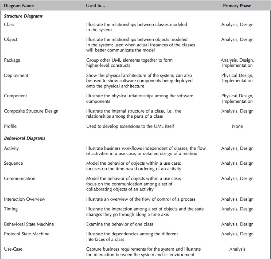
Section 4: UML 2.5 Diagram Summary
Section 5: Summary
Depending on where in the development process the system is, different diagrams play a more important role.
In some cases, the same diagramming technique is used throughout the development process.
- In that case, the diagrams start off very conceptual and abstract.
- As the system is developed, the diagrams evolve to include details that ultimately lead to generating and developing code.
In other words, the diagrams move from documenting the requirements to laying out the design.
Overall, the consistent notation, integration among the diagramming techniques, and application of the diagrams across the entire development process make the UML a powerful and flexible language for analysts and developers.