The student will be able to assess and apply Object-Oriented analysis
and design methods like use cases to express user requirements, UML modeling, and other
OO approaches.
Understand the rules and style guidelines for sequence diagrams.
Understand the processes used to create sequence diagrams.
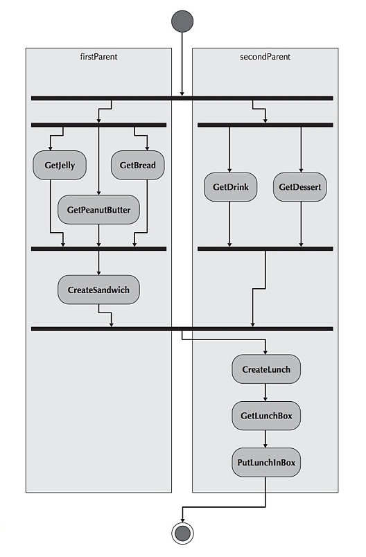
The behavior of a use case can be described by means of activity diagrams and state diagrams,
interaction diagrams (sequence and communication diagrams), as well as textual use cases, where appropriate.
A sequence diagram is a dynamic model that shows the objects that participate in a use case
and the explicit sequence of messages that are passed between those objects over time for one
use case in a defined interaction.
Because sequence diagrams emphasize the time-based ordering of the activity that takes
place among a set of objects, they are very helpful for understanding real-time specifications
and complex use cases.
Typically, an analyst develops a set of instance sequence diagrams, each of which depicts
a single scenario within the use case. A scenario is a single executable path through a use case.
Sequence diagrams can help capture required objects and classes involved in the scenario and show
the order of interactions between the objects needed to carry out the functionality of the scenario.
You can use one or more sequence diagrams to enact a use case diagram. A sequence diagram is built
for each use case in a use case diagram. Each sequence diagram specifies the main interaction steps to
be achieved for each task (i.e. use case).
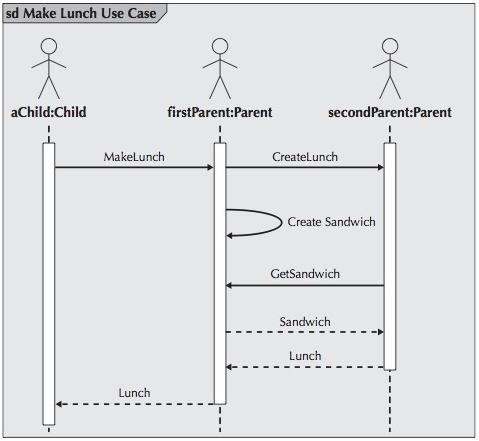
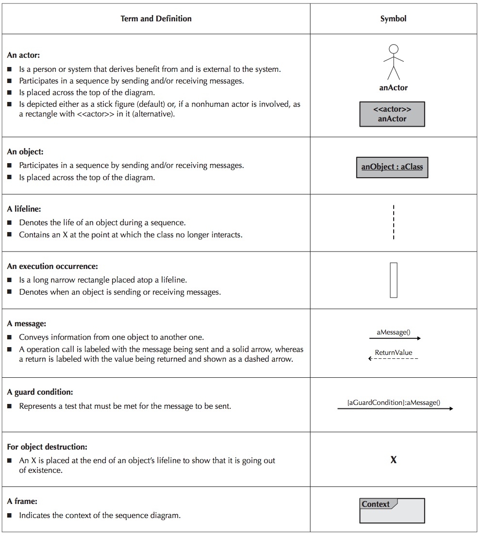
Actors and objects that participate in the sequence are placed across the top of the diagram using actor
symbols from the use case diagram and object symbols from the object diagram.
Notice that the actors and objects in the sequence diagram above are aChild, firstParent, and secondParent.
For each of the objects, the name of the class of which they are an instance is given after the object’s
name (e.g., firstParent is an instance of the Parent class).
Lifeline
A dotted line runs vertically below each actor and object to denote the lifeline of the actors and objects over time.
When objects continue to exist in the system after they are used in the sequence diagram, then the lifeline continues
to the bottom of the diagram.
In some cases an object creates a temporary object, in which case an X is placed at the end of the lifeline at the
point where the object is destroyed.
For example, a shopping cart object in a Web commerce application is used for temporarily capturing line
items for an order, but once the order is confirmed, the shopping cart is no longer needed.
In this case, an X would be located at the point at which the shopping cart object is destroyed.
Execution Occurrence
A thin rectangular box, called the execution occurrence, is overlaid onto the lifeline to show when the classes are
sending and receiving messages.
Messages
A message is a communication between objects that conveys information with the expectation that activity will ensue.
In the case of using sequence diagrams to model use cases, two types of messages are typically used:
operation call and return.
Operation call messages passed between objects are shown using solid lines connecting two objects with an arrow
on the line showing which way the message is being passed.
Argument values for the message are placed in parentheses next to the message’s name.
The order of messages goes from the top to the bottom of the page, so messages located higher on the
diagram represent messages that occur earlier on in the sequence, versus the lower messages that occur
later.
A return message is depicted as a dashed line with an arrow on the end of the line portraying the
direction of the return.
The information being returned is used to label the arrow.
However, because adding return messages tends to clutter the diagram, unless the return messages add a
lot of information to the diagram, they can be omitted.
At times a message is sent only if a condition is met.
In those cases, the condition is placed between a set of brackets, [ ].
The condition is placed in front of the message name.
However, when using a sequence diagram to model a specific scenario, conditions
are typically not shown on any single sequence diagram.
Instead, conditions are implied only through the existence of different sequence diagrams.
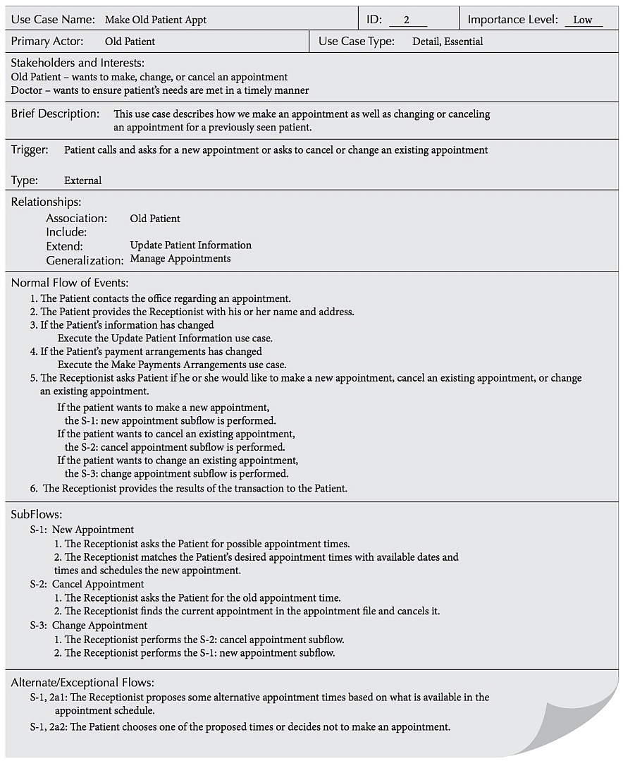
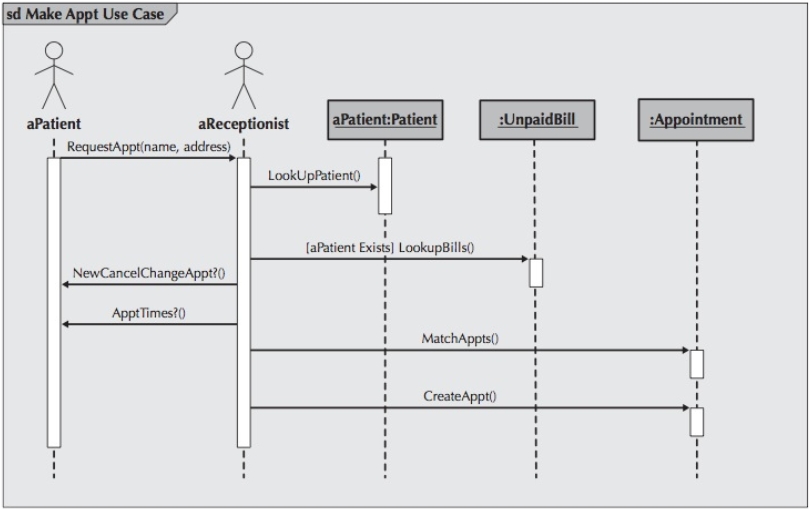
Recall the example use case from the Activity Diagrams for Make Old Patient Appointment
The following sequence diagram depicts the objects and messages for the
Make Old Patient Appt use case, which describes the process by which an existing patient creates
a new appointment or cancels or reschedules an appointment for the doctor’s office appointment
system. In this specific instance, the Make Old Patient Appt process is portrayed.
Try to have the messages not only in a top-to-bottom order but also, when possible, in a
left-to-right order. The sequence diagram is easier to interpret if the messages are ordered
as much as possible in the same way. To accomplish this, order the actors and objects along
the top of the diagram in the order that they participate in the scenario of the use case.
If an actor and an object conceptually represent the same idea, one inside of the software
and the other outside, label them with the same name. In fact, this implies that they exist in
both the use-case diagram (as an actor) and in the class diagram (as a class). At first glance,
this might seem to lead to confusion. However, if they do indeed represent the same idea, then
they should have the same name.
The initiator of the scenario—actor or object—should be the drawn as the farthest left item
in the diagram.
When there are multiple objects of the same type, be sure to include a name for the object
in addition to the class of the object. Otherwise, you can simply use the class name.
Show return values only when they are not obvious and they actually add information for the
reader of the diagram. This reduces clutter.
Align message names and return values near the arrowhead of the message and return arrows,
respectively. This makes it much easier to interpret the messages and their return values.
The following is a six-step process used to create a sequence diagram.
Determine the context of the sequence diagram.
The context of the diagram can be a system, a use case, or a scenario of a use case (most common).
The context of the diagram is depicted as a labeled frame around the diagram.
Identify the actors and objects that participate in the sequence being modeled — i.e., the actors and
objects that interact with each other during the use-case scenario.
The actors were identified during the creation of the functional model, whereas the objects are
identified during the development of the structural model.
These are the classes on which the objects of the sequence diagram for this scenario will be based.
Set the lifeline for each object.
To do this, you need to draw a vertical dotted line below each class to represent the class’s
existence during the sequence.
An X should be placed below the object at the point on the lifeline where the object goes out
of existence.
Add the messages to the diagram by drawing arrows to represent the messages being passed from object
to object, with the arrow pointing in the message’s transmission direction.
The arrows should be placed in order from the first message (at the top) to the last (at the
bottom) to show time sequence.
Any parameters passed along with the messages should be placed in parentheses next to the
message’s name.
If a message is expected to be returned as a response to a message, then the return message
is not explicitly shown on the diagram.
Place the execution occurrence on each object’s lifeline by drawing a narrow rectangle box over
the lifelines to represent when the classes are sending and receiving messages.
Validate the sequence diagram.
Ensures that it depicts all of the steps in the process to guarantee that the sequence
diagram completely represents the underlying process.