The student will be able to assess and apply Object-Oriented analysis
and design methods like use cases to express user requirements, UML modeling, and other
OO approaches.
Understand the rules and style guidelines for behavioral state machines.
Understand the processes used to create behavioral state machines.
Be able to create behavioral state machines.
Understand the relationship between the behavioral models and the structural
and functional models.
The behavior of a use case can be described by means of activity diagrams and state diagrams,
interaction diagrams (sequence and communication diagrams), as well as textual use cases, where appropriate.
Objects often pass through a variety of states over the course of their existence.
For example, a patient can change over time from being new to current to former
based on his or her status with the doctor’s office.
A behavioral state machine is a dynamic model that shows the different states through
which a single object passes during its life in response to events, along with its responses
and actions.
The behavioral state machine shows the different states of the object and what events
cause the object to change from one state to another.
Typically, behavioral state machines are not used for all objects, but instead are used
with complex objects to further define them and to help simplify the design of algorithms
for their methods.
Behavioral state machines should be used to help understand the dynamic aspects of a
single class and how its instances evolve over time, unlike interaction diagrams that
show how a particular use case or use case scenario is executed over a set of classes.
In order to understand state transition diagrams, we must be familiar with states,
events, transitions, actions, and activities.
States
The state of an object is defined by the value of its attributes and its relationships
with other objects at a particular point in time.
For example, a patient might have a state of new, current, or former.
The attributes or properties of an object affect the state that it is in; however,
not all attributes or attribute changes will make a difference.
For example, think about a patient’s address.
Those attributes make very little difference to changes in a patient’s state.
However, if states were based on a patient’s geographic location (e.g., in-town
patients were treated differently than out-of-town patients), changes to the patient’s
address would influence state changes.
Events
An event is something that takes place at a certain point in time and changes a value
or values that describe an object, which, in turn, changes the object’s state.
It can be a designated condition becoming true, the receipt of the call for
a method by an object, or the passage of a designated period of time.
The state of the object determines exactly what the response will be.
Transitions
An object typically moves from one state to another based on the outcome of an
action triggered by an event.
A transition is a relationship that represents the movement of an object from one
state to another state.
Some transitions have a guard condition, which is a Boolean expression that
includes attribute values, which allows a transition to occur only if the condition
is true.
Actions
An action is an atomic, nondecomposable process that cannot be interrupted.
From a practical perspective, actions take zero time, and they are associated
with a transition.
Activities
In contrast, an activity is a nonatomic, decomposable process that can be interrupted.
Activities take a long period of time to complete, and they can be started and
stopped by an action.
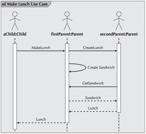
Try as you might, you cannot forget the Make Lunch example. Here is the sequence diagram:
And the communication diagram:
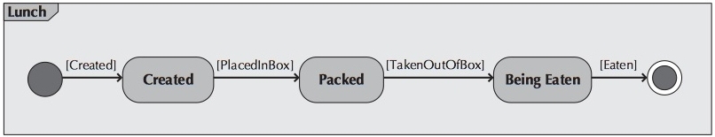
The following figure shows a behavioral state machine diagram for making a School Lunch:
There is obviously additional information that has been captured about the lunch object.
The scenario of the sequence diagram and communication diagram did not include information
regarding the lunch being taken out of the box or being eaten.
This implies additional use cases and/or use case scenarios that would have to be included
in a system dealing with lunch processing.
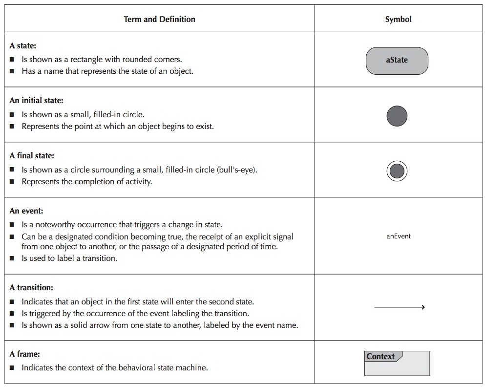
A state is a set of values that describes an object at a specific point in time and
represents a point in an object’s life in which it satisfies some condition, performs
some action, or waits for something to happen.
A state is depicted by a state symbol, which is a rectangle with rounded corners with
a descriptive label that communicates a particular state.
However, there are two exceptions – an initial state is shown using a small,
filled-in circle, and an object’s final state is shown as a circle surrounding a small,
filled-in circle.
These exceptions depict when an object begins and ceases to exist, respectively.
Arrows
Arrows are used to connect the state symbols, representing the transitions between states.
Each arrow is labeled with the appropriate event name and any parameters or conditions
that may apply.
Frames
As in the other behavioral diagrams, in many cases it is useful to explicitly show the
context of the behavioral state machine using a frame.
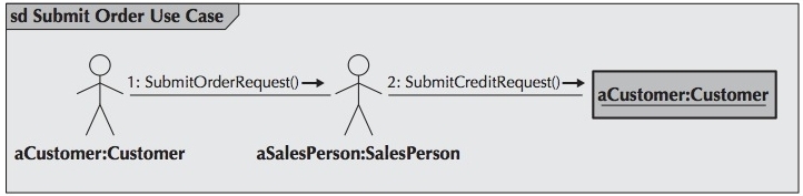
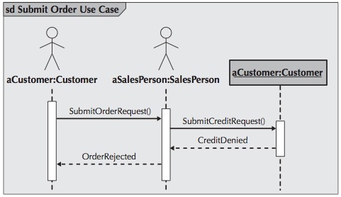
First we'll see the sequence diagram for submitting an order:
And here is the communication diagram:
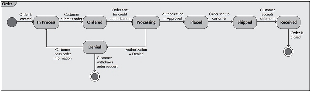
The following behavioral state machine deals with the life cycle of an order.
Again, there is quite a bit of additional information contained in this behavioral state machine.
For an order-processing system, additional sequence and communication diagrams would be
necessary to completely represent all the processing associated with an order object.
Obviously, because behavioral state machines can uncover additional processing
requirements, they can be very useful in filling out the complete description of an
evolving system.
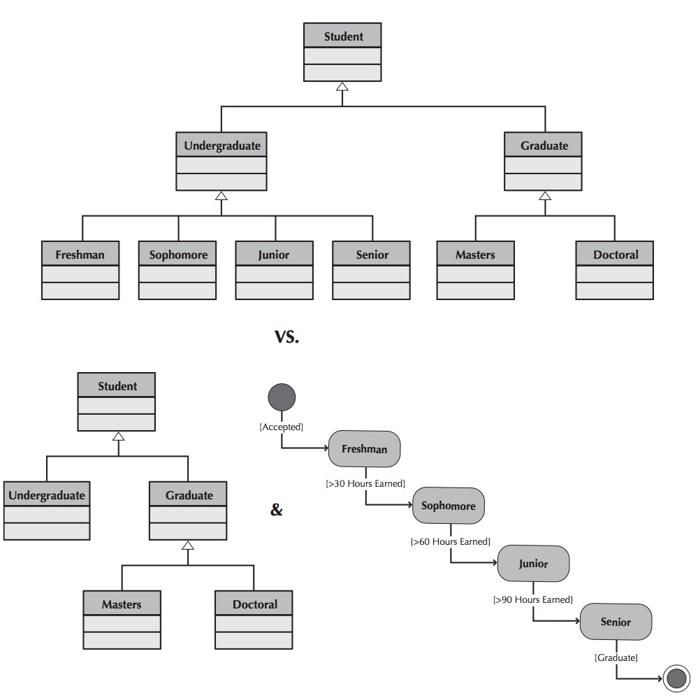
For example, in the figure below are Freshman, Sophomore, Junior, and Senior
subclasses of the class Undergraduate or are they states that an instance of the
Undergraduate class goes through during its lifetime?
In this case, states is the better answer.
When trying to identify all potential classes during structural modeling, you
might actually identify states of the relevant superclass instead of subclasses.
This is another example of how tightly intertwined the functional, structural,
and behavioral models can be.
From a modeling perspective, although we eventually removed the Freshman,
Sophomore, Junior, and Senior subclasses from the structural model, capturing
that information during structural modeling and removing it based on discoveries
made during behavioral modeling were preferable to omitting it and taking a chance
of missing a crucial piece of information about the problem domain.
Remember, object-oriented development is iterative and incremental. As we progress to a correct model of the problem domain, we will make many mistakes.
Create a behavioral state machine for objects whose behavior changes based on the state of the object.
In other words, do not create a behavioral state machine for an object whose behavior is always
the same regardless of its state, because such objects are too simple.
The initial state should be drawn in the top left corner of the diagram and the final
state should be drawn in the bottom right of the diagram.
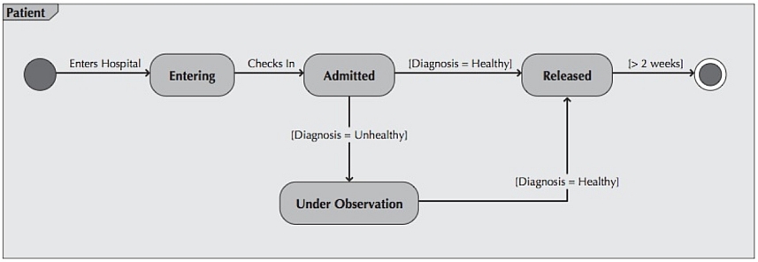
Make sure that the names of the states are simple, intuitively obvious, and descriptive.
For example in Example 3 the state names of the patient object are Entering, Admitted,
Under Observation, and Released.
Question black hole and miracle states.
These types of states are problematic for the same reason black hole and miracle
activities are a problem for activity diagrams.
Black hole states, states that an object goes into and never comes out of,
most likely are actually final states.
Miracle states, states that an object comes out of but never went into,
most likely are initial states.
Be sure that all guard conditions are mutually exclusive (not overlapping).
For example, in example 3, the guard condition [Diagnosis = Healthy] and the guard
condition [Diagnosis = Unhealthy] do not overlap.
However, if you created a guard condition of [x >= 0] and a second guard condition
[x <= 0], the guard conditions overlap when x = 0, and it is not clear to which state
the object would transition, resulting in confusion.
All transitions should be associated with a message and operation.
Otherwise, the state of the object could never change.
While this may be stating the obvious, there have been numerous times that analysts
forget to go back and ensure that this is indeed true.
Behavioral state machines are drawn to depict an instance of a single class from a class diagram.
Typically, the classes are very dynamic and complex, requiring a good understanding of
their states over time and events triggering changes.
Examine your class diagram to identify which classes undergo a complex series of state
changes and draw a diagram for each of them.
Here is a five-step process used to build a behavioral state machine.
Determine the context of the behavioral state machine.
The context is shown in the label of the frame of the diagram.
The context of a behavioral state machine is usually a class, but could be could be a set
of classes, a subsystem, or an entire system.
Identify the various states that an object will have over its lifetime.
This includes establishing the boundaries of the existence of an object by identifying
the initial and final states of an object.
We also must identify the states of an object.
The information necessary to perform this is gleaned from reading the use-case descriptions,
talking with users, and relying on the requirements-gathering techniques that you learned earlier.
An easy way to identify the states of an object is to write the steps of what happens to an
object over time, from start to finish, similar to how the normal flow of events section of a
use case description would be created.
Determine the sequence of the states that an object will pass through during its lifetime.
Using this sequence, the states are placed onto the behavioral state machine in a
left-to-right order.
Identify the transitions between the states of the objects and to add the events, actions,
and guard conditions associated with the transitions.
The actions are typically operations contained within the object.
Also, guard conditions can model a set of test conditions that must be met for
the transition to occur.
At this point in the process, the transitions are drawn between the relevant states
and labeled with the event, action, or guard condition.
Validate the behavioral state machine.
Make sure that each state is reachable and that it is possible to leave all states
except for final states.
If an identified state is not reachable, either a transition is missing or the state was
identified in error.
Only final states can be a dead end from the perspective of an object’s life cycle.