


Section 0: Module Objectives or Competencies
| Course Objective or Competency | Module Objectives or Competency |
|---|---|
| The student will be able to assess and apply Object-Oriented analysis and design methods like use cases to express user requirements, UML modeling, and other OO approaches. | Understand the process used to create use case diagrams. |
Section 1: Overview
Here is a Use Case Introduction:
The Unified Process is said to be Use-Case Driven:
A use case diagram is a depiction of a system’s behavior or functionality under various conditions as the system responds to requests from users.
- A use case diagram describes sequences of actions a system performs that yield an observable result of value to a particular actor.
- Provides a logical model of what a system does without describing how the system does it.
Functional requirements are specified in a collection of use case diagrams. Each feature or user goal of the system must have a use case diagram written for it.
- Use case diagrams serve as a view of the system requirements.
- Based on the interactions and relationships of individual use cases.
Video Overview
Here is a video overview of Use Cases:
This video provides a few more details:
Confusing Terms
The use of similar terms can be confusing – there are use case elements, use case diagrams, and collections of use case diagrams.
From a graphical standpoint...
- A use case element is single ellipse.
- An individual use case diagram may include one or more use case elements.
- A collection of use case diagrams is made up of individual use case diagrams.
- A use case scenario is a single path through the use case.
From the standpoint of what they represent...
- A use case element represents a single system process.
- A use case diagram represents the processes that together accomplish one system requirement.
- A collection of use case diagrams models the functional requirements of a system. A complete set of use cases specifies all the different ways to use the system, and thus defines all behavior required of the system.
We will also discuss use case descriptions, which provide a textual means to more fully document the different aspects of each individual use case diagrams.
Use cases also involve happy paths. No wonder the stick figures look so happy!
- In the context of software or information modeling a happy path is a default scenario featuring no exceptional or error conditions, and comprises the sequence of activities executed if everything goes as expected.
Section 2: Benefits of Use Case Diagrams
- Identify all the actors in the problem domain.
- Actions that need to be completed are also clearly shown on the use case diagram.
- Simplicity and lack of technical detail.
- Compared to traditional methods, use case diagrams are easy to write and to read.
- Use case diagrams force the developers to think through the design of a system from the perspective of a user.
- Use case diagrams engage the users in the requirements process, helping them to understand the proposed system and giving them a way to communicate their needs.
- Use case diagrams give context for the requirements of the system.
- Use case diagrams provide an ordering mechanism for requirements; they show the ordering of things.
- Use case diagrams are a critical tool in the analysis process, helping to understand what the system needs to do.
- Use case diagrams are a critical tool in the design and implementation process, reducing the risk of inconsistencies when moving from requirement to design to implementation.
- Use case diagrams carry over directly into the testing process.
- Use case diagrams serve as inputs to the user documentation.
-
Use cases play many roles in the Unified Process:
-
Use case diagrams involve happy stick figures.
Section 3: Elements of Use Case Diagrams
Basic Concepts
Sequences of actions
- The sequences of actions describe a set of functions performed, an algorithmic procedure, or any other internal process that produces a result.
- The set is invoked when the actor initiates the use case by providing some input to the system.
- An action is atomic; that is, it is performed entirely or not at all.
System performs
- The system works for the actor.
- It exhibits the functionality described in the use case and takes its orders from the actor as to when to do what.
An observable result of value
- The use case must be “of value” to a user.
- The system must do something for the user.
A particular actor
- The particular actor is the individual or device that initiates the action.
Use Case Components
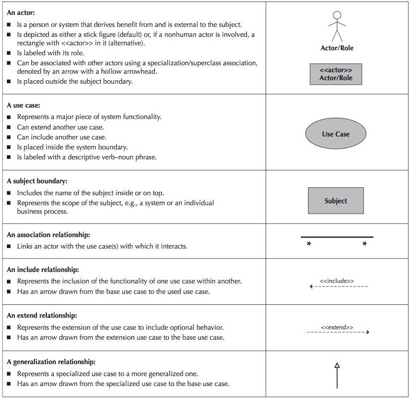
A use case diagram contains four components.
- The boundary, which defines the system of interest in relation to the world around it.
- The actors, usually individuals involved with the system defined according to their roles.
- The use cases (or use case elements), each of which represents a process that is relevant for one or more actors and/or participants in the system.
- The relationships between and among the actors and the use cases (or use case elements).
Note that each use case must include
- An actor that initiates an event.
- The event that triggers a use case.
- The use cases that perform the actions triggered by the event.
Elements
Actors
What exactly is an actor?
An actor is something that interacts with the system
- Refers to a particular role of a user of the system.
- Similar to external entities; they exist outside of the system.
Types of Actors
-
Divided into two groups
-
Primary actors:
- Supply data or receive information from the system.
- Provide details on what the use case should do.
-
Supporting actors:
- Help to keep the system running or provide help.
- The people who run the help desk, the analysts, programmers, and so on.
-
Primary actors:
-
Most actors represent user roles, but actors can also be external systems.
-
Users:
- Users act on the system and this is the most common type of actors.
-
Other Systems or Applications:
- Most software systems interact with other systems or applications. These are also actors.
-
A Device:
- Input and output devices can also be actors.
-
Users:
- An actor is a role, not a specific user; one user may play many roles, and an actor may represent many users.
Use Case (element)
Use case represents a single system function.
- Represented as an ellipse on a use case diagram.
Subject boundary
Subject boundary includes all the relevant use cases.
- A boundary is the dividing line between the system and its environment.
- Use cases are within the boundary.
- Actors are outside of the boundary.
- Represented as a box.
Association
Association is a connection between an actor and a use case.
- Depicts a usage relationship.
- Association does not indicate data flow.
- Actors are connected to use cases with lines.
- Use cases are connected to each other with arrows.
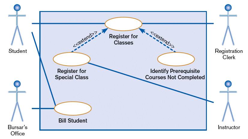
Extend relationship is an association between two use cases where one adds new behaviors or actions to the other.
- Extends a use case by adding new behavior or actions.
- Specialized use case extends the general use case.
Include relationship is an association between two use cases where one use case uses the functionality contained in the other.
- Indicates a use case that is used (invoked) by another use case.
- Links to general purpose functions, used by many other use cases.
Section 4: Identifying Major Use Cases
Note that the average number of Use Cases per project is 88 (source).
-
Review the business specifications and identify the actors involved and their goals.
- May use agile stories, problem definition objectives, user requirements, or a features list.
- A user story is similar to a single scenario of a use case (link).
- Identify the subject’s boundaries
- Identify the high-level events (business processes) and develop the primary use cases that describe those events and how the actors initiate them.
-
Review each primary use case to determine the possible variations of flow through the use case.
-
Split or combine some to create the right size (3 to 9 use cases per system).
- If the project team discovers many more than eight use cases, this suggests that the use cases are too small or that the system boundary is too big.
- If more than nine use cases exist, the use cases should be grouped together into packages (i.e., logical groups of use cases) to make the diagrams easier to read and keep the models at a reasonable level of complexity. More on packages here.
- Identify additional use cases
-
Split or combine some to create the right size (3 to 9 use cases per system).
- The context-level data flow diagram could act as a starting point for creating a use case.
- The use case ends when the customer goal is complete.
Video Example
Here is a video demonstrating modeling use case elements:
Section 5: Create a Use Case Diagram
Building the Use Case Model
Let's start with a video:
- It is a top down process that depends on first building a context model of the system.
- That model is successively refined until the detailed behaviors are understood.
- It is an iterative process in which the various steps are revisited over time.
Steps in Building the Use Case Model
-
Identify and Describe the Actors: Identify all actors that interact with the system.
- Who uses the system?
- Who gets information from the system?
- Who provides information to the system?
- Where in the organization is the system used?
- Who supports and maintains the system?
- What other systems use the system?
-
Identify the Use Cases and Write a Brief Description: Identify what actors need to do to accomplish
their tasks.
- What will the actor use the system for?
- Will the actor create, store, change, remove, or read data in the system?
- Will the actor need to inform the system about external events or changes?
- Will the actor need to be informed about certain occurrences in the system?
-
Consider the following template:
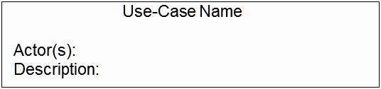
- Identify the Actor and Use Case Relationship: Although only one actor can initiate a use case, many use cases involve the participation of multiple actors. Each use case must be analyzed to see what actors interact with it.
-
Outline the Individual Use Cases: Before developing detailed use cases for the system, outlines of
each should be developed. Of particular interest at this point is the flow of events, including the
basic and alternate flows.
-
Basic flow:
- What event starts the use case?
- How does the use case end?
- How does the use case repeat some behavior?
-
Alternate flow:
- Are there optional situations in the use case?
- What odd cases might happen?
- What variants might happen?
- What may go wrong?
- What may not happen?
- What kind of resources can be blocked?
-
Basic flow:
-
Refine the Use Cases: At some point later in the project lifecycle, the time will be right to refine the use cases developed. At that time there are a number of additional factors to be considered.
- All alternate flows, including exception conditions: Identifying primary alternate flows is straightforward, but flows due to exception conditions may not be clear initially.
- Pre- and Post-conditions: The refinement process will start to identify state information that controls the behavior of the system. (More on pre- and post-conditions)
Drawing a Use Case Diagram:
- Place and draw the use case
- Place and draw the actors
- Draw the subject boundary
- Add the associations
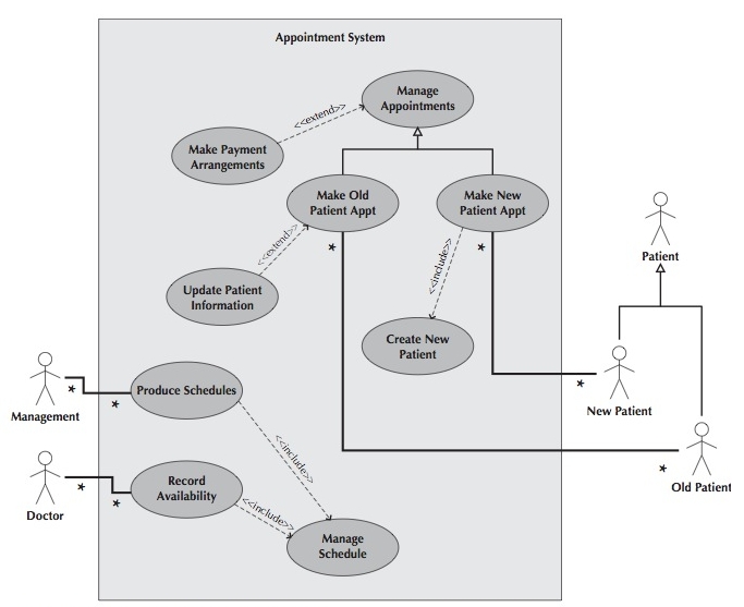
Graphical Example
Patient Appointment System Use Case Diagram
Video Example #1
Here is a video demonstrating a use case diagram for an ATM:
Video Example #2
Here is a video demonstrating a use case diagram for a Maintain Curriculum process:
Section 6: Types of Use Cases
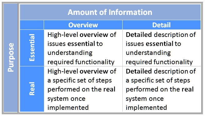
Overview Use Case
An overview use case is used to enable the analyst and user to agree on a high-level overview of the requirements.
- Typically, overview use cases are created very early in the process of understanding the system requirements, and they document only basic information about the use case, such as its name; ID number; primary actor; type; a brief description; and the relationships among the actors, actors and use cases, and use cases.
- These can easily be created immediately after the creation of the use case diagram.
Detail Use Case
Once the user and the analyst agree upon a high-level overview of the requirements, the overview use cases are converted to detail use cases.
- A detail use case typically documents, as far as possible, all the information needed for the use case.
- These can be based on the activities and control flows contained in the activity diagrams.
Essential Use Case
An essential use case is one that describes only the minimum essential issues necessary to understand the required functionality.
- For example, an essential use case in a doctor office might say that the receptionist should attempt to match the patient’s desired appointment times with the available times.
- Essential use cases are implementation independent.
Real Use Case
A real use case goes farther than an essential use case and describes a specific set of steps.
- For example, a real use case might say that the receptionist should look up the available dates on the calendar using Google Calendar to determine if the requested appointment times were available.
- Real use cases are detailed descriptions of how to use the system once it is implemented.
- Real use cases tend to be used only in the design, implementation, and testing.
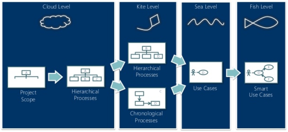
Section 7: Levels of Granularity
Use cases exist at different levels of granularity, or degree of detail in the use case description.
Alistair Cockburn (2000), leading authority on use cases, describes five levels of granularity, also referred to as altitude metaphors known as Cloud level, Kite level, Sea level, Underwater level and Clam level.
Use case level refers to degree of detail in the use case description, and there are five suggested levels (Cockburn, 2000):
- Cloud – as seen from clouds: enterprise level
- Kite – "birds-eye view": business unit or department level
- Sea – sea-level view: user goals
- Fish – below sea-level: functional or sub-functional
- Clam – bottom of the sea: most detailed
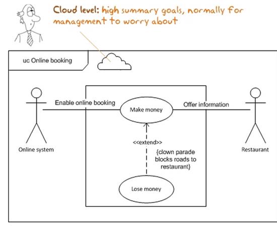
Cloud Level
The Cloud Level is the highest level, or enterprise level. At this level a use case represents ways of getting to highly summarized goals, such as “advertise goods”, “sell goods to customers”, “manage inventory”, “manage the supply chain”, and “optimize shipping”. There may only be four to five cloud-level use cases for the entire organization.
These are very high level and involve multiple user goals. Too high up to be of interest to software development projects, and far too high level to generate code.
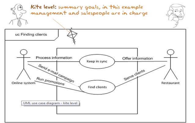
Kite Level
The Kite Level is lower than the Cloud Level but still a high level, providing an overview. This level is still mostly concerned with summary goals, but is slightly more detailed. The kite-level use case may be at the business unit or department level and is a summary of goals. Examples of kite-level use cases would be to “register students”, or if working with a travel company, “make an airline reservation”. Kite-level use cases represent high level processes that take place over several hours, days, or weeks and involve many steps. They are generally too high level to be interesting to software development projects and generating code.
Kite-level use cases show how the sea-level use cases fit into wider business interactions. Kite-level use cases are usually business use cases, whereas sea and fish levels are system use cases. Most use cases should be at the sea level.
Sea Level
Sea-level use cases are usually created for user goals. These often have the greatest interest for users and are easiest for a business to understand. They are usually written for a business activity. Examples are “register a continuing student”, “add a new customer”, “place an item in a shopping cart”, and “order checkout”.
A single use case at this level describes a single elementary business process, and realizes a single user (actor) goal. The core use cases are at “sea level.” Sea-level use cases typically represent a discrete interaction between a primary actor and the system. Such use cases will deliver something of value to the primary actor and usually take from a couple of minutes to half an hour for the primary actor to complete.
Fish Level
At the Fish Level a use case shows lots of detail, often at a functional or subfunctional level. Examples are “choose a class”, “pay academic fees”, “save as file”, “look up the airport code for a given city”, and “produce a list of customers after entering a name”.
This level is concerned with the implementation of the system, underlying the diagram at sea level. Fish-level use cases are needed to accomplish user goals, typically can be used and reused. These use cases, along with sea-level use cases, provide a good basis for generating code that handles the software's behavior.
Clam Level
Clam-level use cases are the most detailed use cases, at a subfunction level. Examples might be a “secure logon validation”, “insert record into database”, or “add new field using dynamic HTML”. These are not usually written out in detail as use cases, but rather appear as steps in another use case, most likely at the fish level.
Video Explanation
Here is an excruciating video demonstrating use case levels:
Related Links
Section 8: Verification and Validation
Use cases must be verified and validated before beginning structural and behavioral modeling.
Walkthroughs are often used.
- Perform a review of the models and diagrams created so far.
-
Performed by individuals from the development team and the client (very interactive).
- Facilitator: schedule and set up the meeting.
- Presenter: the one who is responsible for the specific representation being reviewed.
- Recorder (scribe) to take notes and especially to document errors.
Rules for Verification & Validation
- Ensure one recorded event in the flows of the use case description for each action/activity on the activity diagram
- All objects in an activity diagram must be mentioned in an event of the use case description
- The sequence of the use case description should match the sequence in the activity diagram
- One and only one description for each use case
- All actors listed in a use case description must be shown on the use case diagram
- Stakeholders listed in the use case description may be shown on the use case diagram (check local policy)
- All relationships in the use case description must be depicted on the use case diagram
- All diagram-specific rules must be enforced
Section 9: Resources
- GenMyMdodel Design Tool
- PDF Notes
- Use Case Diagram Tutorial
- Example and Discussion
- UML Use Case Diagram Examples
- Use Case Taxi Example (Word file)
- Use Case Exercise (Word file) [Use Case Exercise Solution] (Word file)
- Use Case Modelling Flashcards
- Use Case Flashcards
-
Video: UML 2.0 Use Cases
-
Video: Use Case Diagrams