Section 0: Module Objectives or Competencies
| Course Objective or Competency | Module Objectives or Competency |
|---|---|
| The student will be able to analyze database requirements and determine the entities involved in the system and their relationship to one another. | The student will be able to recognize and model entities, attributes, and relationships. |
| The student will be able to recognize and model one-to-one, one-to-many, and many-to-many relationships. | |
| The student will be able to determine connectivity and cardinality and model them correctly in the logical database. | |
| The student will be able to recognize and depict the composite relationships needed to model many-to-many relationships. |
Section 1: Overview
An information model consists of
- objects
- relationships
- attributes of objects and relationships
- constraints (rules and restrictions) on objects, relationships, and attributes
- operations to be performed on the model
This class will focus on the first three....
Section 2: Developing An E-R Diagram
Database design is an iterative process
- begins with narrative of organization's operations and procedures
- basic E-R model is graphically depicted and presented for review
- additional objects, attributes, and relationships will be added during review
- E-R model will be modified to include new additions
- review process begins again...
- process terminates only when end users and designers agree that the diagram correctly represents the organization's activities and functions
Section 3: Approaches to Identifying Object Types and Relationships
Report requirements analysis
- information can be gathered by examining the business forms and reports that an organization uses.
Functional analysis
- emphasizes business functions as a starting point, such as auditing, taking inventory, etc.
- focuses on identifying the major functions and activities to be performed, and determining the objects needed to support their execution.
Transaction analysis
- emphasizes events, such as order arrival, using state transition diagrams.
Scenario analysis
- emphasizes identifying a central activity, such as manufacturing plastic products, or sales, as a starting point.
Section 4: Steps of Functional Analysis
- Identify the domain of information, i.e., set the boundaries.
-
Identify all business functions that are included in the domain of information.
For each business function: -
Identify the business activities of the business function.
For each business activity: - Identify all object types that are input to the business activity.
- Identify all object types that are modified by the activity.
- Identify all object types that are produced by the business activity.
- Identify all relationships that are established between participating object types by the business activity.
- Identify all object types or relationships that are used but not changed by the business activity (ex. government regulations).
- Identify all object types that control or implement the business activity (ex. policies, government regulations).
- Identify all operations performed on the object types and relationships by the business activity. Examples of operations on objects: DISPLAY, CREATE. Examples of operations on relationships: MODIFY TREATMENT, PRINT TREATMENT LIST.
Note that forms, reports, receipts, etc., are generated by the system and are not objects.
- That said, forms, reports, receipts, etc. can provide the designed with information about specific attributes of the objects that they are associated with.
Section 5: Example
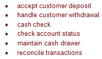
Analyze the activities of a bank teller as a system using functional analysis. A teller can process deposits and withdrawals as well as cash checks. The teller can also provide information about account status. While processing these transactions, the teller must maintain an accurate balance of their cash drawer so that they can reconcile transactions at the end of their shift.
List business functions:
List the objects under each, if necessary:
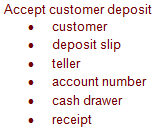
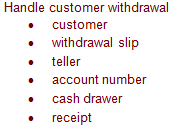


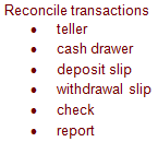
List of Objects:

Evaluation of Objects:

So? (click me)
Section 6: Steps in Developing an E-R Diagram
Steps:
- select relevant entities
- define an initial set of relations
- identify attributes of the entities
- define the connectivity and cardinality for the relations by querying the end user extensively
Start by choosing some object – maybe the most independent or dominant object.
Example: customer – most independent, least number of cross-referenced attributes.
Section 7: E-R Diagram for Banking System
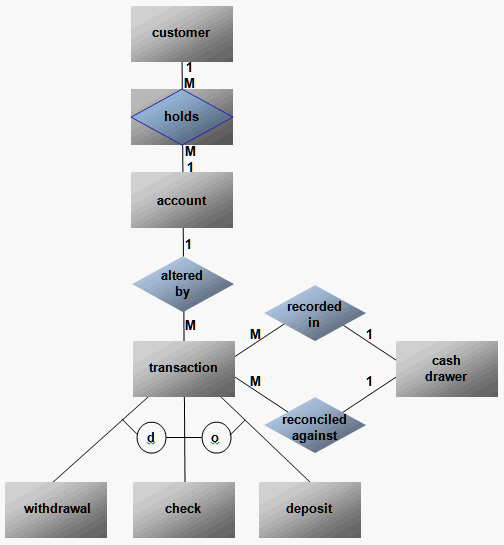
Section 8: Converting an E-R Model into a Database Structure
List attributes:
- CUSTOMER (C#, CNAME, CADDR,....)
- HOLDS (C#, A#)
- ACCOUNT (A#, A_BALANCE, A_TYPE, .... , C#)
- TRANSACTION (T#, T_TYPE, T_AMT, T_DATE, A_BALANCE, TELLER#, A#)
- WITHDRAWAL (W#, W_TYPE, T#)
- DEPOSIT (D#, D_TYPE, T#)
- CASH_DRAWER (CD#, CD_BALANCE)
- RECORDED IN (T#, CD#)
Discussion...(click below)
Correct Solution
- CUSTOMER (C#, CNAME, CADDR,....)
- HOLDS (C#, A#)
- ACCOUNT (A#, A_BALANCE, A_TYPE, .... )
- TRANSACTION (T#, T_TYPE, T_AMT, T_DATE, TELLER#, A#, CD#)
- CASH_DRAWER (CD#, CD_BALANCE)
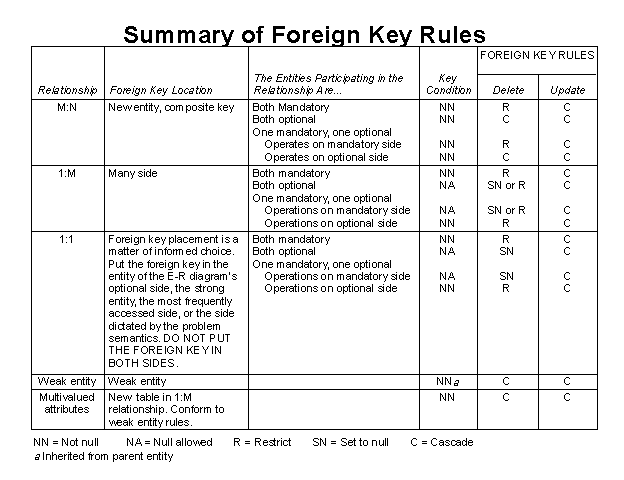
Section 9: Rules Governing Relationships
A general set of rules to help create database tables that meet the required integrity constraints:
- All primary keys must be defined as NOT NULL.
- Define all foreign keys to conform to the following requirements for binary relationships:
1:M Relationships
Create the foreign key by putting the primary key of the "one" as a foreign key in the table of the "many." The "one" side is referred to as the parent table, and the "many" side is referred to as the dependent table. In short, the primary key of "the one" appears as a foreign key in the table of "the many".
Weak Entity
Put the key of the parent table (the "strong" entity) in the weak entity as a foreign key. The key of the weak entity will be a composite key composed of the parent table key and the weak entity candidate key, if any. A new unique ID may be created for the entity as well.
M:N Relationships
Convert M:N relationships to a composite (bridge) entity consisting of (at least) the parent tables' primary keys. The bridge entity primary key is thus a composite key, and each individual component of the composite key also serves as a foreign key.
1:1 Relationships
If both entities are in a mandatory participation in the relationship and they do not participate in other relationships it is most likely that the two entities should be combined into one entity.
If two separate entities are used, the primary key of one of the entities is placed as a foreign key in the most frequently accessed entity. It may also serve as the primary key.
Section 10: Closing Notes
Even as entities, relationships, attributes, and constraints are the focus of attention, end-user requirements such as performance, security, shared access, data integrity, etc., must be considered.
The designer must consider processing requirements and verify that the update, retrieve, and delete options work correctly, and that all necessary reports can be generated from the available entities and attributes.
A design is of little use if the final product is incapable of delivering all specified query and reporting requirements.


