The student will be able to assess and apply Object-Oriented analysis
and design methods like use cases to express user requirements, UML modeling, and other
OO approaches.
Understand the rules and style guidelines for communication diagrams.
Understand the processes used to create communication diagrams.
The behavior of a use case can be described by means of activity diagrams and state diagrams,
interaction diagrams (sequence and communication diagrams), as well as textual use cases, where appropriate.
A communication diagram, also called a collaboration diagram, can
show how the members of a set of objects collaborate to implement a use case or a use case
scenario.
They can also be used to model all the interactions among a set of collaborating objects,
portraying how dependent the different objects are on one another.
A communication diagram is essentially an object diagram that shows message-passing
relationships instead of aggregation or generalization associations.
Communication diagrams are very useful for showing patterns of activity that occur over
a set of collaborating classes.
Communicaion diagrams can be very useful in partitioning, an upcoming topic in OO Design Considerations.
Communication diagrams emphasize the flow of messages through a set of objects, whereas the
sequence diagrams focus on the time ordering of the messages being passed.
A communication diagram helps to understand the flow of control over a set of collaborating
objects or to understand which objects collaborate to support business processes.
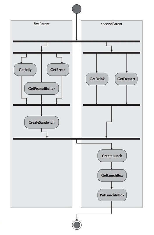
Recall the activity diagram for making a School Lunch from the last chapter.
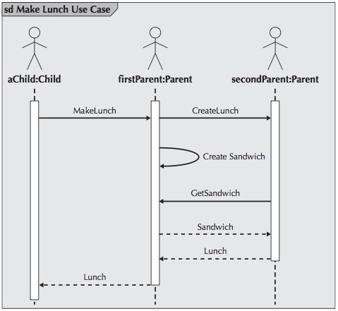
That was followed by the sequence diagram derived from that scenario:
The following figure shows a communication diagram for making a School Lunch:
Differences
The diagram above is equivalent to the sequence diagrams for making a school lunch.
When comparing the communication diagrams to the sequence diagram, quite a bit
of information is lost. For example, the CreateSandwich() message is nowhere to be found.
However, the primary purpose of the communication diagram is to show how the different
actors and classes interact, and this is exactly the information that is included.
Simplification
When a communication diagram is fully populated with all the objects, it can become very complex
and may need to be simplified through the use of packages (i.e., logical groups of classes).
In the case of communication diagrams, its objects are grouped together based on the
messages sent to and received from the other objects.
Actors and objects that collaborate to execute the use case are placed on the communication diagram
in a manner to emphasize the message passing that takes place between them.
Notice that the actors and objects in the figure above are the same ones in sequence diagram
from the first example: aChild, firstParent, and secondParent.
Again, as with the sequence diagram, for each of the objects, the name of the class of which they
are an instance is given after the object’s name (e.g., firstParent:Parent).
Differences
Unlike the sequence diagram, the communication diagram does not have a means to explicitly show
an object being deleted or created.
It is assumed that when a delete, destroy, or remove message is sent to an object, it
will go out of existence, and a create or new message will cause a new object to come into existence.
Another difference between the two interaction diagrams is that the communication diagram never
shows returns from message sends, whereas the sequence diagram can optionally show them.
Association
An association is shown between actors and objects with an undirected line.
Messages are shown as labels on the associations.
Included with the labels are lines with arrows showing the direction of the message being sent.
For example, an association is shown between the aChild and firstParent actors, and
another is shown between firstParent and secondParent.
The firstParent actor sends the CreateLunch() message to the secondParent actor, and the
secondParent actor sends the GetSandwich() message to the firstParent actor.
In the above figure the MakeLunch() message is the first message sent, whereas the
CreateLunch() and the GetSandwich() messages are the second and third messages sent, respectively.
Conditional Messages
Like the sequence diagram, the communication diagram can represent conditional messages. The
condition is indicated in square brackets preceding the message, and the message is sent only if
the condition is met.
Repeated Messages
If a message is repeatedly sent, an asterisk is placed after the sequence number.
Self-Delegation Messages
Self-delegation is shown as an association that loops onto an object. The message is shown
as the label of the association.
The following is a communication diagram for the Make Old Patient Appt use case, which
describes the process by which an existing patient creates a new appointment or cancels or
reschedules an appointment for the doctor’s office appointment system. In this specific
instance, the Make Old Patient Appt process is portrayed.
Note that the LookupBills() message is conditional and is sent only if the [aPatient exists]
condition is met.
Use the correct diagram for the information you are interested in communicating with the user. Communication diagrams allow the team to easily identify a set of objects that are intertwined. Do not use communication diagrams to model process flow. Instead, you should use an activity diagram with swimlanes that represent objects. On the other hand, it would be very difficult to “see” how the objects collaborated in an activity diagram.
When trying to understand the sequencing of messages, a sequence diagram should be used instead of a communication diagram. As in the previous guideline, this guideline essentially suggests that you should use the diagram that was designed to deal with the issue at hand. Even though communication diagrams can show sequencing of messages, this was never meant to be their primary purpose.
The following is a five-step process used to create a communication diagram.
Remember that a communication diagram is basically an object diagram that shows message-passing
relationships instead of aggregation or generalization associations.
Determine the context of the communication diagram.
The context of the diagram can be a system, a use case, or a scenario of a use case (most common).
The context of the diagram is depicted as a labeled frame around the diagram.
Identify the objects (actors) that participate in the collaboration together.
the objects that participate in the collaboration are instances of the classes
identified during the development of the structural model.
it is likely that additional objects, and hence classes, will be discovered because the
underlying development process is iterative and incremental.
In addition to the communication diagram being modified, the sequence diagrams and
structural model probably also have to be modified.
Additional functional requirements might also be uncovered, hence requiring the functional
models to be modified as well
Lay out the objects and their associations.
Lay out the objects (actors) and their associations on the communication diagram
by placing them together based on the associations that they have with the other
objects in the collaboration.
By focusing on the associations between the objects (actors) and minimizing the
number of associations that cross over one another, we can increase the understandability
of the diagram.
Add the messages to the associations between the objects.
Do this by adding the name of the message(s) to the association link between the
objects and an arrow showing the direction of the message being sent.
Each message has a sequence number associated with it to portray the time-based
ordering of the message.
Validate the communication diagram.
This guarantee that the communication diagram faithfully portrays the underlying
process(es) by ensuring that all steps in the process are depicted on the diagram.