The student will be able to assess and apply Object-Oriented analysis
and design methods like use cases to express user requirements, UML modeling, and
other OO approaches.
Package diagrams show the packages and their relationships.
Depending on where a package is used, packages can participate in different types of relationships.
For example, in a class diagram, packages represent groupings of classes so aggregation and
association relationships are possible.
Collaborations, partitions, and layers are modeled as packages in UML.
Collaborations are normally factored into a set of partitions, which are typically placed
on a layer.
Partitions can be composed of other partitions.
It is possible to have classes in partitions, which are contained in another partition, which is
placed on a layer, and represented using packages in UML.
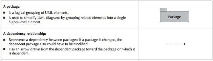
A new relationship, the dependency relationship, is useful in package diagrams.
A dependency relationship represents the fact that it is possible that a change in
one package could cause a change to be required in another package, i.e., a modification
dependency exists between two packages.
A dependency relationship is portrayed by a dashed arrow.
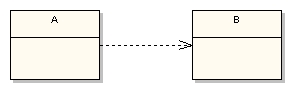
What does a dependency relationship represent? In the UML diagram above the dependency means that
class A uses class B, but that class A does not contain an instance of class B as part of its own state.
It also means that if class B’s interface changes it will likely impact class A and require it to change.
Use dependency to indicate that, for example, class A receives an instance of class B as a parameter to at
least one of its methods.
You would also use dependency to indicate that class A creates an instance of class B local to one of
its methods.
Dependency is a directed relationship which is used to show that some UML element or a set of elements
requires, needs or depends on other model elements for specification or implementation.
Because of this, dependency is called a supplier-client relationship, where supplier provides something
to the client, and thus the client is in some sense incomplete while semantically or structurally dependent
on the supplier element(s).
Modification of the supplier may impact the client elements.
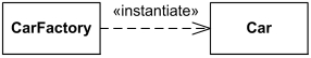
Interpretation: CarFactory class depends on the Car class.
CarFactory depends on the Car class. Car class could be defined without the knowledge of
CarFactory class, but CarFactory requires Car for its definition because it produces Cars.
The Car class is instantiated by the CarFactory class.
For many years UML specifications provided an incorrect example of dependencies.
At the class level, there could be many causes for dependencies among classes. For example,
if the protocol for a method is changed, then this causes the interface for all objects of this
class to change.
Therefore, all classes that have objects that send messages to the instances of the
modified class might have to be modified.
Capturing dependency relationships among the classes and packages helps the organization
in maintaining object-oriented information systems.
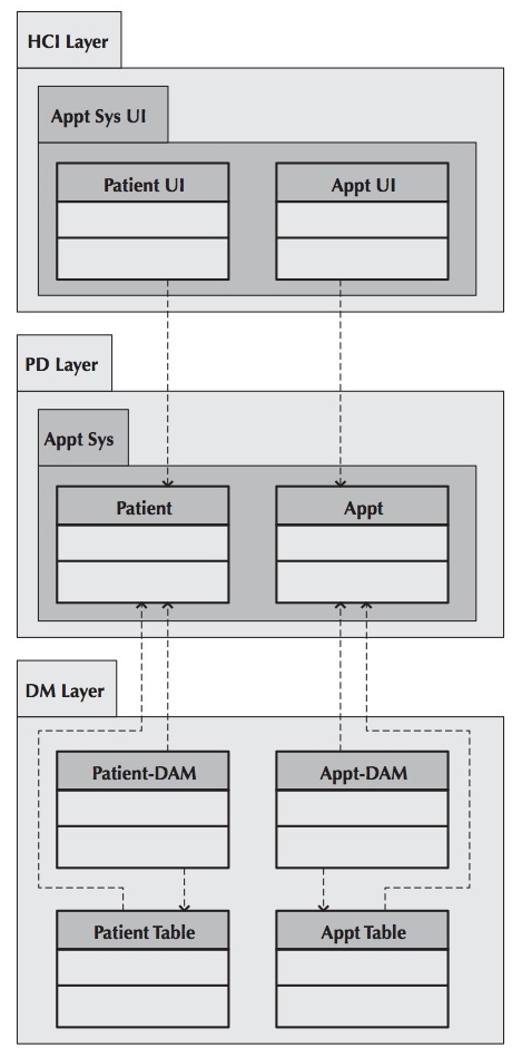
A simple package diagram, based on the appointment system example from the previous chapters, is shown in the figure below.
The figure portrays only a very small portion of the entire system.
The Patient UI, Patient-DAM, and Patient Table classes depend on the Patient class.
The Patient-DAM class depends on the Patient Table class.
The same can be seen with the classes dealing with the actual appointments.
By isolating the Problem Domain classes (such as the Patient and Appt classes) from the actual
object-persistence classes (such as the Patient Table and Appt Table classes) through the use of
the intermediate Data Management classes (Patient-DAM and Appt-DAM classes), the Problem Domain
classes are isolated from the actual storage medium.
This greatly simplifies the maintenance and increases the reusability of the problem domain classes.
Use package diagrams to logically organize designs.
Specifically, use packages to group classes together when there is an inheritance,
aggregation, or composition relationship between them, or when the classes form a collaboration.
Observe semantic relationships.
When inheritance, aggregation, or association relationships exist between packages:
Try to depict support inheritance relationships vertically, with the package
containing the superclass being placed above the package containing the subclass.
Try to use horizontal placement to support aggregation and association relationships,
with the packages being placed side by side.
Dependency relationships should also observe semantic relationships.
A dependency relationship implies that there is at least one semantic relationship
between elements of the two packages.
The direction of the dependency is typically from the subclass to the
superclass, from the whole to the part, and with contracts, from the client
to the server.
A subclass is dependent on the existence of a superclass, a whole is
dependent upon its parts existing, and a client can’t send a message to a
nonexistent server.
Use case package diagrams should include the actors.
Including the actors and the associations that they have with the use cases grouped
in the package allows the diagram’s user to better understand the context of the diagram.
Use simple but descriptive names for each package.
Simple but descriptive names provide the package diagram user with enough information
to understand what the package encapsulates.
Make packages cohesive.
The classes contained in the package should belong together.
A simple rule to follow when grouping classes together in a package is that the more the classes
are reliant on each other, the more likely they belong together in a package.
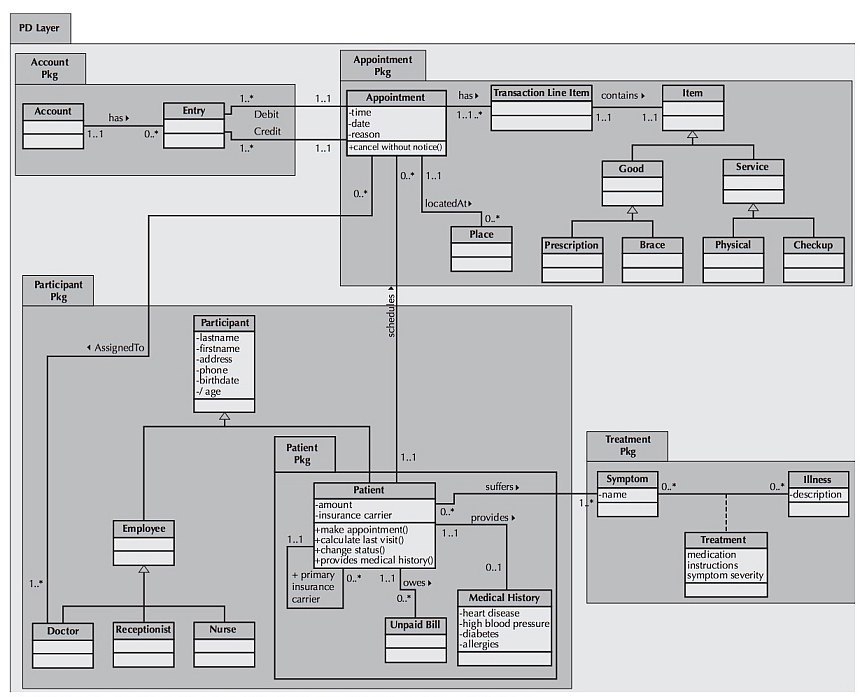
Revisiting the appointment system again, consider the problem domain layer to be the context.
Cluster the classes together into partitions based on the relationships that the classes share.
The relationships include generalization, aggregation, the various associations, and the message
sending that takes place between the objects in the system.
To identify the packages in the appointment system, we should look at the different analysis
models, e.g., the class diagram, the communication diagrams, and the CRUDE matrix.
Classes in a generalization hierarchy should be kept together in a single partition.
Place the clustered classes together in a partition and model the partitions as packages.
See the figure below.
Identify dependency relationships among packages.
This is done by reviewing the relationships that cross the boundaries of the packages to
uncover potential dependencies.
In the appointment system, we see association relationships that connect the Account Pkg
with the Appointment Pkg (via the associations between the Entry class and the Appointment
class), the Participant Pkg with the Appointment Pkg (via the association between the Doctor
class and the Appointment class), the Patient Pkg, which is contained within the Participant
Pkg, with the Appointment Pkg (via the association between the Patient and Appointment classes),
and the Patient Pkg with the Treatment Pkg (via the association between the Patient and Symptom
classes).
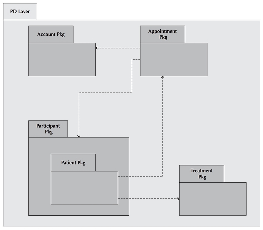
Lay out and draw the diagram including only the packages and their dependencies.
Place the packages and dependency relationships in the diagram.
In the case of the Appointment system, there are dependency relationships between the
Account Pkg and the Appointment Pkg, the Participant Pkg and the Appointment Pkg, the Patient
Pkg and the Appointment Pkg, and the Patient Pkg and the Treatment Pkg.
To increase the understandability of the dependency relationships among the different
packages, a pure package diagram that shows only the dependency relationships among the
packages can be created.
First, the identified packages must make sense from a problem domain point of view.
For example, in the context of an appointment system, the packages in the figure below (Participant,
Patient, Appt, Account, and Treatment) seem to be reasonable.
Second, all dependency relationships must be based on message-sending relationships on the communications
diagram, cell entries in the CRUDE matrix, and associations on the class diagram.