The student will be able to assess and apply Object-Oriented analysis
and design methods like use cases to express user requirements, UML modeling, and
other OO approaches.
Understand the verification and validation of the analysis models.
Understand the transition from analysis to design.
Understand the use of factoring, partitions, and layers.
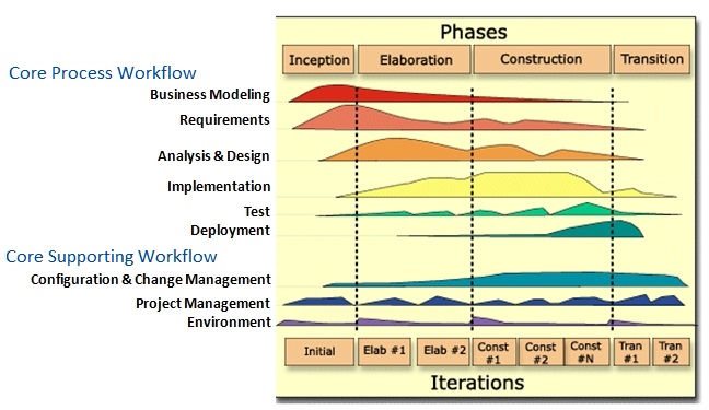
From an enhanced Unified Process perspective, the process is moving from the analysis
workflow to the design workflow, and moving further into the Elaboration phase and partially
into the Construction phase. (diagram)
The major activity that takes place during design is evolving the set
of analysis representations into design representations.
Design includes detailed design of the individual classes and methods
that are used to map out the nuts and bolts of the system and how they are to be stored
Techniques such as CRC cards, class diagrams, contract specification, method
specification, and database design provide the final design details in preparation
for the implementation phase, and they ensure that programmers have sufficient
information to build the right system efficiently.
Design also includes activities such as designing the user interface, system inputs,
and system outputs, which involve the ways that the user interacts with the system.
Before evolving the analysis representations into design representations, the analyst
needs to verify and validate the current set of analysis models to ensure that they
faithfully represent the problem domain under consideration.
This includes testing the fidelity of each model; for example, the analyst must be sure
that the activity diagram(s), use case descriptions, and use case diagrams all describe the
same functional requirements.
It also involves testing the fidelity between the models; for instance, transitions on
a behavioral state machine are associated with operations contained in a class diagram.
The analyst must also ensure that the different models are consistent.
The process of ensuring the consistency among them is known as balancing the models.
The process of ensuring the consistency among the intersections of the analysis models is
known as balancing the models.
Depending on the specific constructs of each actual model, different interrelationships
are relevant.
Balancing Functional and Behavioral Models
Sequence and communication diagrams must be associated with a use case.
Actors on sequence and communication diagrams or CRUDE matrices must be associated
with actors within a use case.
Messages on sequence and communication diagrams, transitions on behavioral state machines
and entries in a CRUDE matrix must relate to activities on an activity diagram and events in
a use case.
All complex objects in activity diagrams must be represented in a behavioral state machine.
Balancing Behavioral and Structural Models
Objects in a CRUDE matrix must be associated with classes.
Behavioral state machine must be associated with objects on a class diagram.
Objects in sequence and communication diagrams must be associated with objects on a
class diagram.
Messages on sequence and communication diagrams and transitions on behavioral state
machines must be associated with operations in a class.
States in a behavioral state machine must match the different values of an attribute
of an object.
Balancing Structural and Functional Models
A class on a class diagram must be associated with at least one use case.
An activity in an activity diagram and an event in a use case description should
be related to one or more operations on a class diagram.
An object node on an activity diagram must be associated with an instance or
an attribute on a class diagram.
An attribute or an association/aggregation relationship on a class diagram
should be related to the subject or object of a use case.
Analysis models focused on functional requirements.
Design models must include non-functional requirements as well.
System performance
System environment issues
Distributed vs. centralized processing
User interface
Database
The system must be maintainable and modifiable, and affordable, efficient and effective.
From an object-oriented perspective, system design models simply refine the system analysis
models by adding system environment (or solution domain) details to them and refining the problem
domain information already contained in the analysis models.
When evolving the analysis model into the design model, first carefully review the use cases
and the current set of classes (their operations and attributes and the relationships between them).
While the analysis models should have already been verified and validated, they must be reviewed
again, but this time by looking at the models of the problem domain through a design lens.
At this point, modifications are made to the problem domain models that will enhance the efficiency
and effectiveness of the evolving system.
Approaches will include factoring, partitions and collaborations, and layers.
Factoring and partitioning are terms closely related to the thought process
involved in developing structure charts,
that is, design so that decision making and work are stratified. Similar topics include
design decomposition or functional decomposition.
The concept of decision-making modules at the top, and worker modules near
the bottom of the modularization sums up factoring and partitioning.
It also demonstrates once again that structured design concepts cannot be dismissed
even if the OO paradigm is embraced.
From a structured design discussion: "This process of breaking functional components
into subcomponents is called factoring. Factoring includes adding read and write modules,
error-handling modules, initialization and termination process, identifying customer modules,
etc. The factoring process is continued until all processes in the DFD are represented in the
structure chart."
Object-oriented decomposition, on the other hand, breaks a large system down into progressively
smaller classes or objects that are responsible for some part of the problem domain.
Factoring
Factoring is the process of separating out a module into a stand-alone module.
If a set of classes has a similar set of attributes and methods it might make sense to factor
out the similarities into a separate class.
If the new class has a superclass relationship to the existing classes, it can be related to
the existing classes through a generalization (a-kind-of) or through an aggregation (has-parts) relationship.
Example: appointment system
If the Employee class had not been identified, it could be identified at this stage by factoring
out the similar methods and attributes from the Nurse, Receptionist, and Doctor classes.
In this case, we would relate the new class (Employee) to the existing classes using the
generalization (a-kind-of) relationship.
By extension we also could have created the Participant class if it had not been previously
identified.
Abstraction and refinement are closely related to factoring.
Abstraction deals with the creation of a higher-level idea from a set of ideas.
Identifying the Employee class is an example of abstracting from a set of lower
classes to a higher one.
In some cases, the abstraction process identifies abstract classes, whereas in
other situations, it identifies additional concrete classes.
Refinement deals with the creation of a detailed class as a more specific form of
a higher-level class.
In the appointment system example, we could identify additional subclasses of
the Employee class, such as Secretary and Bookkeeper.
New classes would be added only if there were sufficient differences among them.
Otherwise, the more general class, Employee, would suffice.
Partitioning
Partitioning involves creating a sub-system of closely collaborating classes.
The primary purpose of identifying partitions is to determine
which classes should be grouped together in design.
Partitions are based on the pattern of activity (messages sent) among the objects
in an object-oriented system.
Patterns of activity are shown by collaborations found in a communication diagram.
Higher coupling among classes may identify partitions (e.g., more messages passed between
objects suggests that they belong in the same partition).
Creating a diagram that combines the class diagram with the communication diagrams can be very
useful to show to what degree the classes are coupled.
Additional approaches for identifying collaborations include analysis of the CRUDE matrix, cluster
analysis, multiple dimensional scaling, or client-server-contract approaches, none of which are covered here.
Basic guidelines
As subsystems are defined (and designed), they should conform to the following design criteria:
Each subsystem should have a well-defined interface through which all communication with the rest
of the system occurs.
With the exception of a small number of communication classes, the classes within a subsystem
should collaborate only with other classes within the subsystem.
The number of subsystems should be kept small.
Subsystems can be partitioned internally to help reduce complexity.
Communication between subsystems is either peer-to-peer or client-server.
Identifying partitions determines which classes should be grouped together.
To successfully evolve the analysis model of the system into a design model of the system, we use layers to
address the system environment information (data management, user interface, and physical architecture).
Each layer represents and separates elements of the software architecture of the evolving system.
MVC
The Model–View–Controller (MVC) architecture is an application of the software engineering principle known
as separation of concerns, which basically stated implies that it is best to segregate
different types of functionality within an application as much as possible.
The idea of separating the different elements of the architecture into separate layers can be traced back
to the MVC architecture.
MVC uses Models to implement the application logic
(problem domain) and Views and Controllers to implement the logic for the user interface.
Views handle the output, and Controllers handle the input.
Since the advent of MVC, many different software layers have been proposed.
The text recommends the following layers on which to base software architecture: foundation, problem
domain, data management, human–computer interaction, and physical architecture.
Each layer limits the types of classes that can exist on it (e.g., only user interface
classes may exist on the human–computer interaction layer).
Foundation
The foundation layer contains classes that are necessary for any object-oriented application to
exist such as those that represent fundamental data types (e.g., integers, real numbers, characters,
strings), classes that represent fundamental data structures, sometimes referred to as container
classes (e.g., lists, trees, graphs, sets, stacks, queues), and classes that represent useful
abstractions, sometimes referred to as utility classes (e.g., date, time, money).
These classes are rarely, if ever, modified by a developer. They are simply used.
The classes found on this layer are typically included with the object-oriented development
environments.
Problem Domain
The problem-domain layer deals with the specific system under development.
Classes must be further detailed so that we can implement them in an effective and efficient
manner, so issues related to factoring, cohesion and coupling, connascence, encapsulation, proper
use of inheritance and polymorphism, constraints, contract specification, and detailed method
design must be considered.
Data Management
The data management layer addresses the issues involving the persistence of the objects contained
in the system.
The Data Access and Manipulation (DAM) classes that appear in this layer deal with how objects
can be stored and retrieved, and allow the problem domain classes to be independent of the storage
used and, hence, increase the portability of the evolving system.
Human–Computer Interaction
The human–computer interaction layer contains classes associated with the View and Controller
idea from MVC.
The primary purpose of this layer is to keep the specific user-interface implementation
separate from the problem domain classes.
Physical Architecture
The physical architecture layer addresses how the software will execute on specific computers
and networks, and includes classes that deal with communication between the software and the
computer’s operating system and the network.
Choosing the appropriate set of classes for this layer involves many design issues such
as the choice of a computing or network architecture (such as the various client-server
architectures), the actual design of a network, hardware and server software specification,
security issues, hardware and software configuration (choice of operating systems; processor
types and speeds; amount of memory; data storage; and input/output technology), standardization,
virtualization, grid computing, distributed computing, and Web services.