Section 0: Module Objectives or Competencies
| Course Objective or Competency | Module Objectives or Competency |
|---|---|
| The student will be able to develop the logical design of the database using data modeling concepts such as entity-relationship diagrams. | The student will be able to explain why Entity-Relationship Modeling is used to analyze and design the logical database model. |
| The student will be able to evaluate and use various E-R modeling approaches such as Chen and Crow's Foot. |
| The student will be able to analyze database requirements and determine the entities involved in the system and their relationship to one another. | The student will be able to recognize and model entities, attributes, and relationships. |
| The student will be able to recognize and model unary, binary, and ternary relationships. | |
| The student will be able to recognize and model one-to-one, one-to-many, and many-to-many relationships. | |
| The student will be able to explain why the one-to-many relationship is the relational ideal. | |
| The student will be able to determine connectivity and cardinality and model them correctly in the logical database. | |
| The student will be able to recognize and model existence dependencies, weak entities, mandatory relationships, and optional relationships. | |
| The student will be able to recognize and depict the composite relationships needed to model many-to-many relationships. | |
| The student will be able to recognize and model recursive entities as well as generalization hierarchies. |
Section 1: Justification
Problem
- Different data views: designers, programmers, and end users see data in different terms
- Different views result in database designs that do not reflect an organization's actual operation, thus failing to meet end-user needs and data efficiency requirements
Requirement
- Need a precise description of the nature of data and the uses of data within an organization
- Reduce ambiguities between database designers, programmers, and end users
- Reduce the difficult real-world complexities to more easily understood abstractions that define entities and the relations among them
Solution
- E-R model is used to consolidate the different views of data at the conceptual level
Section 2: E-R Model
- Entity–relationship modeling was developed for database design in the mid-1970s.
- Chen model: Peter Chen, 1976, MIT
- Crow's foot notation: Gordon Everest, 1976, University of Minnesota Twin Cities
- Here is the ERD tool provided with the textbook.
- Here is a tool that appears able to create both Chen and Crow's Foot models.
- E-R diagrams represent the conceptual database as viewed by the end user
- three main components: entities, attributes, relationships
- since an entity represents a real-world object, the terms entity and object are often used as synonyms
Entities
- Recall that an entity is a person, place, thing, or event for which data is collected and stored.
- An entity corresponds to a table (not to a row) in the relational environment
- A table row is referred to as an entity instance or entity occurrence
- Represented by a rectangle containing the entity's name
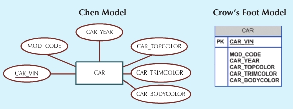
Attributes
- Represented by ovals that are connected to the entity by a line
-
Each oval contains the name of the attribute it represents
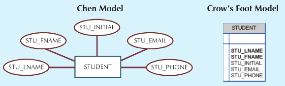
- The primary key attribute is underlined
- Attributes have a domain (set of possible values)
- Attributes may share a domain
-
Attributes are often represented in a frequently used table structure
shorthand using the format
TABLE NAME (KEY ATTRIBUTE1, ATTRIBUTE2, ATTRIBUTE3, ...ATTRIBUTE K)
- Ideally a primary key is composed of only a single attribute, but it is possible to have composite keys that are primary keys composed of more than one attribute ex. COURSE_NUM, SECTION
Importance
Entities will become tables in the physical model, and attributes will become columns of each table.
Section 3: Attribute Types
Simple Attributes
- Simple attributes cannot be subdivided.
Composite Attributes
- Composite attributes (not composite key) can be further subdivided
to yield additional attributes.
- example: ADDRESS
- To facilitate detailed queries, it is often appropriate to change composite
attributes into a series of simple attributes.
- example: ADDRESS can be subdivided into (at least) STREET, CITY, STATE, and ZIP.
Single-Valued Attributes
- Single-valued attribute can have only a single value (SSN).
Multivalued Attributes
- Multivalued attributes can have many values (DEGREE).
-
Multivalued attributes are represented by a double line connecting the attribute
to the entity.

-
Multivalued attributes cannot be implemented directly in a relational DBMS.
-
Solution 1 – additional attributes:
-
Solution 2 – additional entities:
-
Solution 1 – additional attributes:
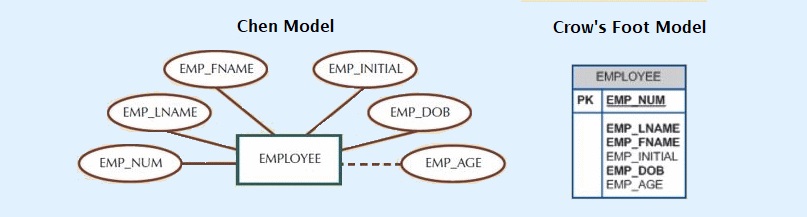
Derived Attributes
- Derived attributes do not physically exist but are derived from other attributes using an algorithm (AGE, SALARY).
-
Derived attributes are represented by a dotted line to connect the
attribute to the entity.
- Here is a discussion of physically storing derived attributes.
Section 4: Relationships
- An association between entities
- Named so that the name is descriptive of the relationship
- Represented by diamond-shaped symbols
- The entities involved in a relationship are referred to as participants
-
Lines connect each participant to the diamond-shaped relationship symbol
- The relationship's degree indicates the number of associated entities or participants
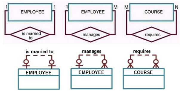
- A unary relationship exists when an association is maintained within a single entity link
- A binary relationship exists when two entities are associated
-
A ternary relationship exists when three entities are associated
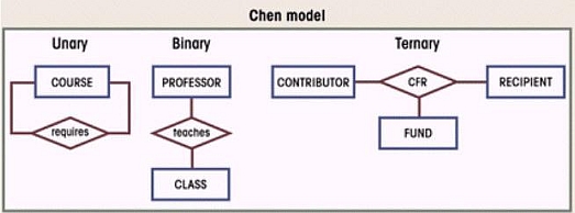
- Higher-order relationships are rare, and are referred to as X-entity relationships
- Binary relationships are most common, and whenever possible higher-order relationships are decomposed in appropriate equivalent binary relationships
Note that the symbols used in the Crow's Foot notation are explained in the next section.
Importance
Relationships are important because they indicate that the entities (tables) involved in the relationship will have a primary key to foreign key link in the physical model.
Section 5: Connectivity
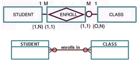
- Used to describe the relationship classification (1:1, 1:M, M:N)
- May also be referred to as cardinality ratio.
-
Chen E-R diagrams indicate connectivity by placing a 1, M, or N near the related entities
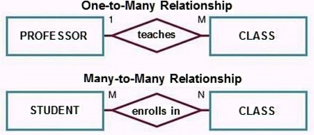
- describes the mapping of associated entity instances in the relationship.
- the correct Chen depiction for 1:M will be shown in the section on Composite Entities.
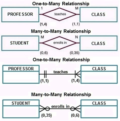
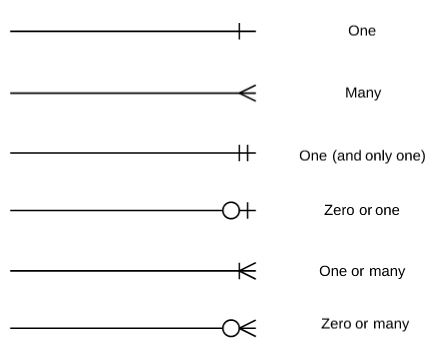
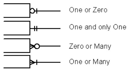
- Crow’s Foot E-R diagrams indicate connectivity by placing a single bar for "1" and a crow's foot for "many" near the related entities
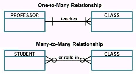
The symbols used to indicate connectivity and cardinality in the Crow's Foot notation are shown below:
Importance
Connectivity (relationship classification) determines which entity (table) involved in the relationship has the primary key and which has a foreign key) in the physical model. For example, in a 1:M relationship the primary key of the "1" appears as a foreign key in the table of the "M". A future lecture will elaborate on Rules Governing Relationships.
Section 6: Cardinality
- May also be referred to as structural constraints.
- Expresses the specific (actual) number of entity occurrences associated with one occurrence of the related entity
- Indicated by placing the appropriate numbers beside the entities
- The actual number of associated entities usually is a function of an organization's policy
- Rules defining cardinality are called business rules, and identifying such rules is an important part of database design
-
Some business rules or constraints cannot be expressed in an E-R diagram, (ex. prerequisites)
and require an accompanying text explanation
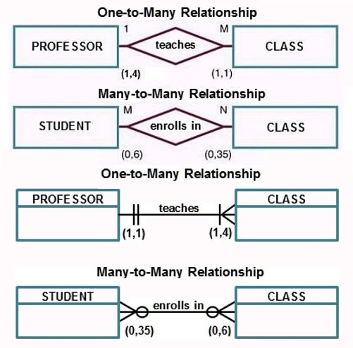
- The correct Chen depiction for 1:M will be shown in the section on Composite Entities.
Importance
Cardinality is a way of expressing some business rules in the logical model. Further, cardinality affects participation (an upcoming topic). If the minimum cardinality is 0, the participation is optional. If the minimum cardinality is greater than 0, the participation is mandatory.
Section 7: Existence Dependence & Weak Entities
Existence Dependency
- Refers to an entity that cannot exist unless one or more other entities also exist
-
More formally, an entity type A is said to be existent dependent on an entity type B if the existence of A depends on the existence of B.
- If B is deleted, A must also be deleted.
- A is subordinate and B is dominant.
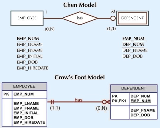
- example: EMPLOYEE and DEPENDENT
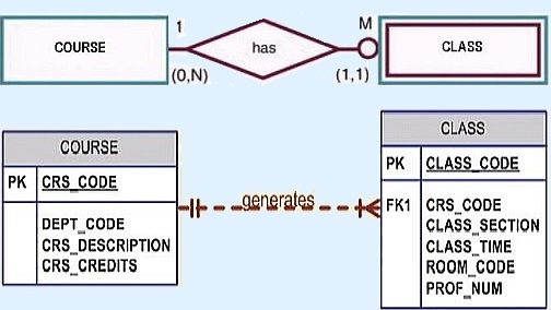
- example: COURSE and CLASS
-
Analyze the business rules to identify whether an entity must exist in a relationship.
-
For example, the business rules might dictate that an address must be associated with a name.
- Such an association indicates a mandatory existence dependency for the relationship between the name and address entities.
-
For example, the business rules might dictate that an address must be associated with a name.
Weak Entity
-
An entity that
- is existence dependent.
- has a primary key that is partially or totally derived from the parent entity in the relationship.
- A weak entity is an entity type that does not have sufficient attributes to form a primary key.
-
A member of a weak entity type is subordinate to the dominant entity with which it is associated.
- Attributes of the dominant entity are combined with those of the subordinate one to form a superkey for the weak entity.
- A superkey of a weak entity type is formed by taking the union of a superkey of the strong entity type on which it is existence dependent and a discriminator.
- A weak entity usually inherits its key identifier from one or more other entities.
- The weak entity type has a set of attributes that depend on a single dominant entity.
- Indicated by a double rectangle.
-
Example 1: Course-Class
-
Example 2: Employee-Dependent
-
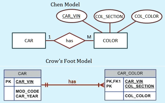
Example 3: Car-Color

-
Again, analyze the business rules to identify whether an entity must exist in a relationship.
- An example of an optional existence dependency could be a business rule related to insurance coverage that says an employee might or might not have children.
Importance
In a physical database, an existence dependency means that there is a requirement for records to exist in a table before any records can be added to the associated table.
A weak entity does not have sufficient attributes to form a primary key so its key is a result of the relationship with the dominant entity.
Section 8: Relationship Participation
Relationship participation is related to existence dependence.
It is sometimes referred to as ordinality, which describes the relationship as either mandatory or optional.
Relationship participation may also be referred to as participation constraints.
-
Mandatory – one participating entity must be associated with one or
more occurrences of the other participating entity in the relationship.
- Existence dependency implies a mandatory relationship.
-
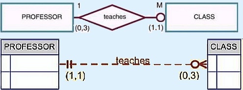
Optional – if one entity occurrence does not require a corresponding
entity occurrence in a particular relationship. In the following example, a professor can
exist without being assigned to teach a class, so the relationship between the two is optional.
-
Optional entities are shown by drawing a small circle on the side of the optional entity:
PROFESSOR (FACULTY#, FACULTY_FNAME, FACULTY_LNAME,...)
CLASS (CLASS#, FACULTY#, ...)
-
Optional entities are shown by drawing a small circle on the side of the optional entity:
- Because an optional relationship is associated with a minimum cardinality of 0, and a mandatory relationship is associated with a minimum cardinality of 1, you may see ordinality defined as the absolute minimum number of times an instance in one entity can be associated with an instance in the related entity.
Importance
In a physical database a mandatory relationship means that there is a requirement for records to exist in a table before any records can be added to the associated table.
In a physical database an optional relationship exists for a table when there is no requirement for any records to exist in that table before any records can be added to the associated table.
Section 9: Recursive Relationship
- One in which a relationship can exist between occurrences of the same entity set.
- This is a nonidentifying, optional relationship in which the same entity is both the parent and the child.
-
Exists in unary relationships
- This is also referred to as a self-referencing relationship and is seen frequently because many business relationships are represented by recursive hierarchies.
Importance
The semantics of recursive relationships are quite difficult to grasp because entities carry out different roles in relationships.
If you're in a silly mood, see this link for further reflection.
Section 10: Composite Entities
Recall the discussion of composite entities from the notes on Relational Databases.
- also called associative entities
- depict the linking tables used to handle M:N relationships
- A many-to-many relationship (M:N) can best be implemented by breaking it up to produce a set of 1:M relationships.
- Recall that a 1:M relationship is the relational ideal.
- bridge entity whose primary key is composed of a combination of the primary keys of the entities being linked
- A composite entity is an entity whose primary key is composed of a combination of the primary keys of the entities that must be linked.
- The composite entity must contain at least the primary keys of the two entities being linked, although additional attributes may be assigned as needed.
-
depicted by a diamond within a rectangle
STUDENT (STU_NUM, ...)
ENROLL (STU_NUM, CLASS_CODE, ENROLL_GRADE)
CLASS (CLASS_CODE, ...)
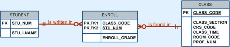
Importance
As noted above, composite entities provide the mechanism by which two entities can be linked in an M:N relationship.
Section 11: Supertypes and Subtypes
- A generalization hierarchy is used to represent entity sets that share common characteristics
- Depict the relationship between a higher-level supertype entity and a lower-level subtype entity
- Represents an "is-a" relationship
- The relationship is one of inheritance: the subtype entity inherits its attributes and its relationships from the supertype entity
- Supertypes and subtypes maintain a 1:1 relationship
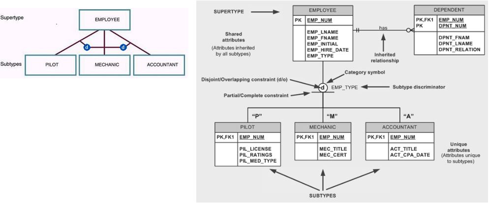
- Nonoverlapping or disjoint subtype entity sets are indicated by the symbol 'd' (PILOT and MECHANIC)
-
Note in the image on the right that the EMPLOYEE table (supertype) has EMP_NUM as its primary key, and
the subtype tables like PILOT have EMP_NUM as the primary key but also EMP_NUM as the foreign key.
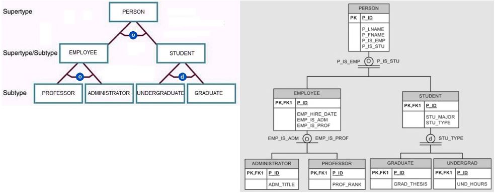
-
Overlapping subtype entity sets are indicated by the symbol 'o' (PROFESSOR and ADMINISTRATOR)
Importance
Supertypes and subtypes make it possible to depict the concept of inheritance that is one of the four principle concepts upon which object-oriented development is based (APIE).
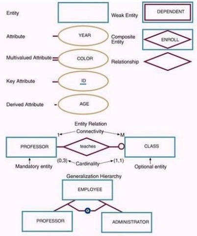
Section 12: E-R Component Summary for Chen Model
Section 13: Modeling Approaches
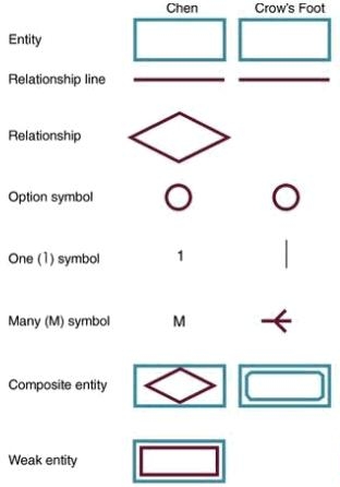
So far we have used the Chen model for our E-R diagrams, but there are other modeling approaches. The Crow's foot model is probably the most widely used, although I prefer Chen for the purpose of teaching concepts. The figure below shows a comparison of the E-R modeling symbols.
Section 14: Examples
The figures below show representations of an invoicing system using the two modeling approaches.